
The modification of a wireless meteo station. Range extension, operation watchdog etc.
In the area of HMCS a meteorological station is installed. It’ s wireless and the transmitted data are aquired by a receiver which interprets the stream of the RF signal into numerical values. Also it has RAM to buffer the timestamped values. The receiver has an RS232 port for connection to a PC or another suitable DTE device.
The meteorological data are used in various research projects related to the behaviour of various building materials.
Data logger
The fact is that the aquisition rate is 1 measurement per minute and soon the provided memory of the receiver overflows resulting loss of data. In the initial setup, the data were tranfered from the receiver to the PC where they are processed and sent to a remote database from where they are extracted from the relevant applications for further processing. The advantages of this architecture that implements a PC is that the data are presented in real time and also the data storing capacity of the PC and the database is practically infinite. The disantvantage is that the PC consumes a lot of power for it’s operation so the UPS operation time is reduced, unless a huge -but expensive- UPS is used. So in case of a prolonged blackout which for unexplained reasons happen always during the weekends, the UPS goes out of operation as the battery is drained and the data are lost because the receiver’ s RAM is overflowed. Moreover a PC is always prone to malfunctions e.g. HD or RAM failure.
We solved the loss of data problem by replacing the PC with a device which fulfils the following conditions:
- communication with the receiver through the serial port (issuing commands to the port)
- offers consinderable storing capacity (in case that the database is closed)
- ability to send the data to the remote database through Ethernet
- the power consumption is minimized
- the cost is low
- it is simple and reliable
Practically we are talking about a single board PC. The selected device is the Raspberry PI model B based on the ARM11 processor which is actually a PC at the size of a credit card. It has interesting features such as:
- Ethernet port 10/100
- USB 2.0 ports (x2)
- HDMI
- SD card slot
The Rasp is powered by means of a cell phone charger through a micro USB connector. The consumption is lower than 3 W which is a significant reduction compared to a energy-thirsty full scale PC consuming roughly 80~100 W.
The connection with the meteo receiver is using a simple USBtoSerial converter. It is cheap and in the market there are numerous suppliers of such converters. The connection can also be done directly using the serial port of the Rasp with the aid of a level shifter.
The data are stored into a 4 GB USB flash stick which satisfies the demand for long term data storage. It should be noted that the USB flash is not the most reliable data storing solution. It has limited timelife and it should be replaced in regular intervals.
The Rasperry board is installed into a plastic box which was drilled to give access to the Ethernet and the USB ports. The top side of the box was drilled to install 3 leds and a switch. The switch is used in conjuction with the USB led to mount and eject the USB flash stick.The leds indicate:
- the normal operation – green
- the USB operation – green
- error – red
The leds are connected to the GPIO connector using appropriate resistors in order to adjust the voltage supplied to each led. The values of resistors depend on the type of the leds. The wiringPi library is implemented for the handling of the relevant pins.
-
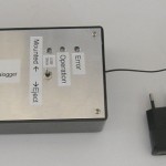
- The datalloger into the box
-
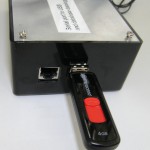
- USB flash connected
-
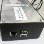
- Communication ports
-
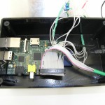
- Inside the box
-
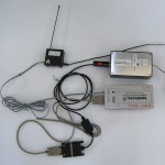
- The meteo receiver connected with the Rasp. It is visible the usbtoserial converter and the antenna of the receiver
-
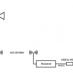
- Meteo station, layout
The Rasp is programmed to run FTP server, so the data stored in the USB flash are remotely accessed.
Operation of the Rasp data logger
The program of the Rasp has the following steps:
- The data logger aquires every 1 minute the latest measurements stored into the meteo receiver RAM.
- The data are processed and converted from imperial to SI units. They are arranged in csv format.
- The processed data are stored into the USB flash stick and also sent to the database through the ethernet connection. If the data are written to the USB flash succesfully, the RASP erases the data from the receiver. If the connection with the database is not possible, the logger buffers temporarily the data and attempts to send them later.
If the reception from the station is lost, the datalogger sends a notification to selected smartphones.
The programming of the Rasp was done by Nikos Silvestros,