National Technical University of Athens
School of Rural & Surveying Engineering
Cartography Laboratory
Analytical hillshading

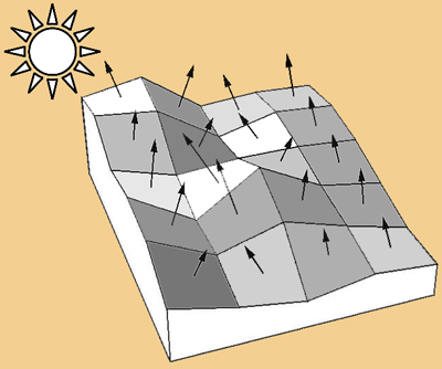
The representation of topographic relief with the method of hill-shading, is based on simulating the effect of natural light on earth’s surface, under some necessary assumptions and simplifications that make the result usable for cartographic purposes. The visual result of the method is formed by the change of the tone of the portrayed surface, which is due to the effect of light and the differentiation of orientation on each point of the surface. Images of shaded relief made for cartographic use, are regularly made up with light coming from north-west, as this has been proved to help all map users, experienced or not, to perceive the forms of earth’s surface relief in an immediate and accurate way.
|
|
|
|
| Formation of a hill-shading image | |
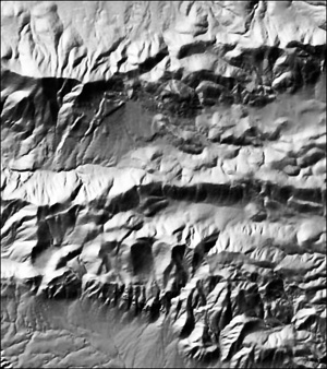 |
In order to represent the main forms of relief which lie in the portrayed area in a better way, the indicative, NW light direction may be optimized, so that those relief forms which dominate, are vertically or diagonally intersected (eg. west or south-west lighting for those forms which are have N-S or NW-SE orientation). However, with the strict adherence on only one lighting direction for the whole map, it is rather difficult to reveal all the relief forms of the represented area, which may have several, different orientations. This is partly treated by adjusting the main direction of light -in a controlled way- on areas facing the light source. But the problem still exists on hillsides which are not properly illuminated (or even not illuminated at all). These areas are shaded by dark grey tones causing visual confusion, hiding the information of relief or making difficult to distinguish the superimposed cartographic symbols.
|
| Hill-shading with indicative, NW lighting | |
 |
 |
| Hill-shading with lighting changed (north), according to dominant relief forms | Hill-shading with adjusting the main direction of light, depending on local relief orientation |
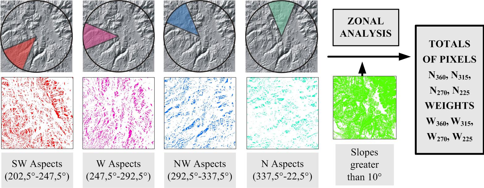
In order to emphasize all the relief forms, regardless of their orientation, it is suggested to use an image of hill-shading based on certain light directions, as a result of unifying four separate hill-shading images corresponding to four main directions: north, north-west, west and south-west. This integration is made by using weights, as following: SMD=WN*[SN]+WNW*[SNW]+WW*[SW]+WSW*[SSW], In addition, the integration can be based on two alternative approaches, which produce different results, in a quantitative and a qualitative level. On the first approach, the integration is made for an entire image, using one, global weight, depending on the percentage of the areas which face towards the light source of this hill-shading image. These areas are horizontally oriented towards a symmetrical range of 45° around the azimuth of light direction and they are identified by using a digital elevation model (areas having slopes less than a certain limit of slope are considered flat, so they are filtered out and ignored). |
|
 |
|
Integration of separate hill-shading images for creating an image of multi-directional hill-shading, with global weights per image, calculated by statistics on orientation values. |
|
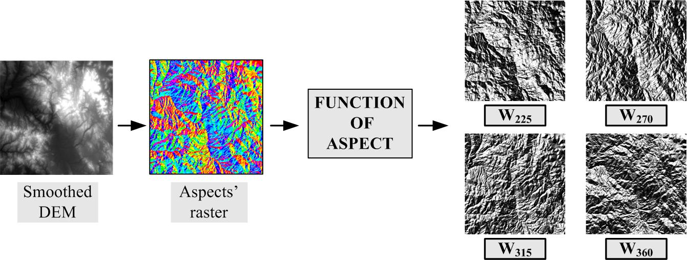
On the second approach, the integration is made on a cell-by-cell basis, while the weights used for the corresponding cells of the separate hill-shading images, are defined as functions of the horizontal aspect of the cell. An example of such function is the following: Wi=[(cos(Aspect-i)+1)]/2ΣWi, where i = 225°, 270°, 315°, 360° and the value of weight Wi is maximized (equals to 1) when the azimuth is equal to angle i andit is minimized when it’s different to it by 180°, while values between 0 and 1 are resulting in all other cases. Practically, this means that those cells of the surface facing to the direction of azimuth i, will participate more than the other cells of this particular hill-shading image in the final combination. The azimuth values are produced by the digital elevation model of the portrayed area, while it is obvious that, in this approach, the weights of each component image are matrices instead of a global, single value. |
|
 |
|
Integration of separate hill-shading images for creating image of mult-directional hill-shading, with weights which are calculated on a cell-by-cell basis, as functions of local orientation. |
|
The integrated image of multi-directional hill-shading does not replace the original hill-shading image -based on the standard or the optimal light direction depending on the global relief characteristics of the area- but these two are combined with this function: [SFIN] = [WM] * [SMO] + [(1-WM)] * [SORIG]. This combination is also made on a cell-by-cell basis and the weight component, WΜ, is a matrix whose values depend on the local incident angle of the light direction, used on the original hill-shading image, i, as follows: [WM] = sin2 [i]. This way, as the incident angle of light gets closer to 90°, the amount of light reaching the surface gets smaller, meaning that the shading tone gets very dark, so that the multi-directional hill-shading is prevailing in the final image. |
|
 |
|
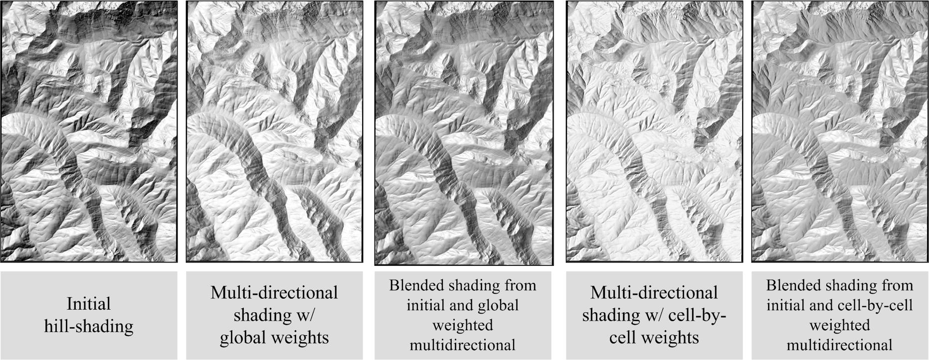
An example of calculating multi-directional hill-shading using the two approaches and combining it with the original hill-shading |
|
|
|
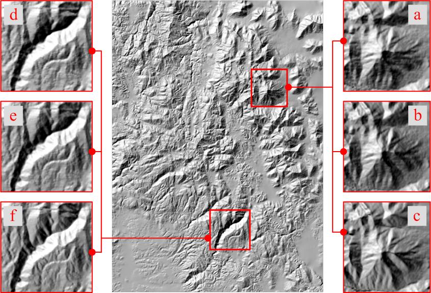
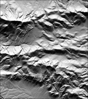
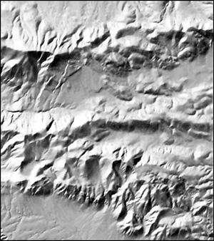
Samples of details from several stages of two approaches: (a) and (d) are from the initial shading,(b) and (e) are from the combination of initial shading with multi-directional made with global weights, and (c) and (f) are from the combination of initial shading with multi-directional made by cell-by-cell weights |
|
The use of global weights, has a more restricted effect in the final result, as the distribution of weights is done in the total images of separate hill-shadings. The use of weights on a cell-be-cell basis has more extended results, because they are applied in each, distinct relief structure. ttention is needed in those cases where the enhancement of lighting is highly increased and contrast is downgraded, because the last is necessary for detecting the facing sides of relief forms, a most important visual cue for hill-shading. It must be pointed out that the spatial resolution of data (the resolution of the digital elevation model), directly related to the scale of the collected height data, is a critical parameter for the quality and the level of detail that is represented in the hill-shaded relief. The more sufficient the resolution and the quality of D.E.M. are, the more impressive and clear the results will be for the portrayed relief model in its final hill-shading image. |
|
Bibliography
|
Edited by Tzelepis Nikos
|