National Technical University of athens
School of Rural & Surveying Engineering
Cartography Laboratory
Eye-tracking and cartography

Eye
Tracking is the methodology of measuring and recording the eye
movements relative to the head position of an observer or that of
capturing the gaze on a visual scene. The meaning of visual scene is
wide and it is possible to be related to an analog product (for example
an analog map) or to a digital product (for example a digital map) that
is depicted on a computer monitor or on a television display or
projected with an appropriate device to a flat surface. Also, it is
possible that the natural surface might be the referred visual scene.
|
|
The geometry of the system operator – observer - EyeTracker |
|
The Eye Tracker is a tool for the tracking of gaze observer during the observation of visual scenes on a computer monitor. The basic components of the system are: the recording device-hardware and the processing software. The Eye Tracker is embedded in a computer machine, which has an additional card for graphics. This contributes to the support of two monitors; the first one is used by the tracker's operator (primary monitor) and the second is used to project visual scenes. The recording device in the central processing unit (CPU) consists of a board connected on the motherboard and externally of a system attached to the observer's optical system. The system of attachment supports the existence of a camera and an infrared LED for each eye of optical system. The system's geometry is integrated by a mechanism that stabilizes the position of the optical system of the observer. The Eye Tracker also provides the opportunity of “extending” visual scene to physical surfaces, as it includes a third camera placed on the system attached to the observer's head. |
|
The geometry of the system camera – infrared LED – mechanism for head stabilization |
|
The system’s function is accomplished by a set of sequential operations. The infrared LED, which is located under the observer's eye, illuminates the eyeball while its image is being capturing by the camera that is placed next to the infrared LED. The illumination of the infrared LED allows the discrimination between regions of pupil and iris. Furthermore, the camera also captures the corneal reflection by applying a predefined threshold. The center of the pupil and the position of corneal reflection are detected by using segmentation algorithms. For each observer, the system creates a transformation that corresponds to every movement of central vision and the relative movement on the stimuli that is depicted on the secondary monitor. The generation of this function occurs through a process of auto-calibration, which takes place for each observer. After defining the appropriate function, the Tracker is able to detect each movement on stimuli scene or each eye movement that occurs on the natural surface. |
|
Diagram with the system's operations |
|
The
Tracker uses three different methods to detect the visual center. The
recording system detects the center of vision by locating the center of
the pupil (pupil location method) or locating the position of the
corneal reflection (glint location method) or computing the vector
between pupil and the position of corneal reflection (pupil-glint
vector). |
|
The detection of the center of pupil (left image) and the detection of pupil and corneal reflection (right image) |
|
The EyeTracker is a useful system for implementing cartographic experiments or similar experiments related to the process of the visual search of psychological studies, as well as, for advertisements or computer software evaluation. The system opens innovative experimental ways to support research on cartography, because it provides recordings of the image of visual trace while capturing the time of the observation, that indicates the “way” and the fixation points that occur during the observation of a scene, a stimuli or an event. |
|
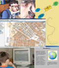
The visual trace during the search of a symbol on a cartographic background |
|
Bibliography
|
Edited by
Vassilios Krassanakis
|